Motorola GSM Hardware Information
I have scanned the guts of some Mot phones- Generally they have identical design - In the later revisions / models smaller packages are used for the chips (TSOP instead of PLCC etc..) and the latest ones use 2.7 volt technology.
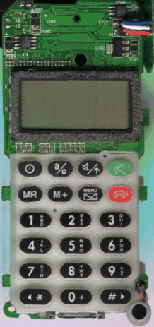
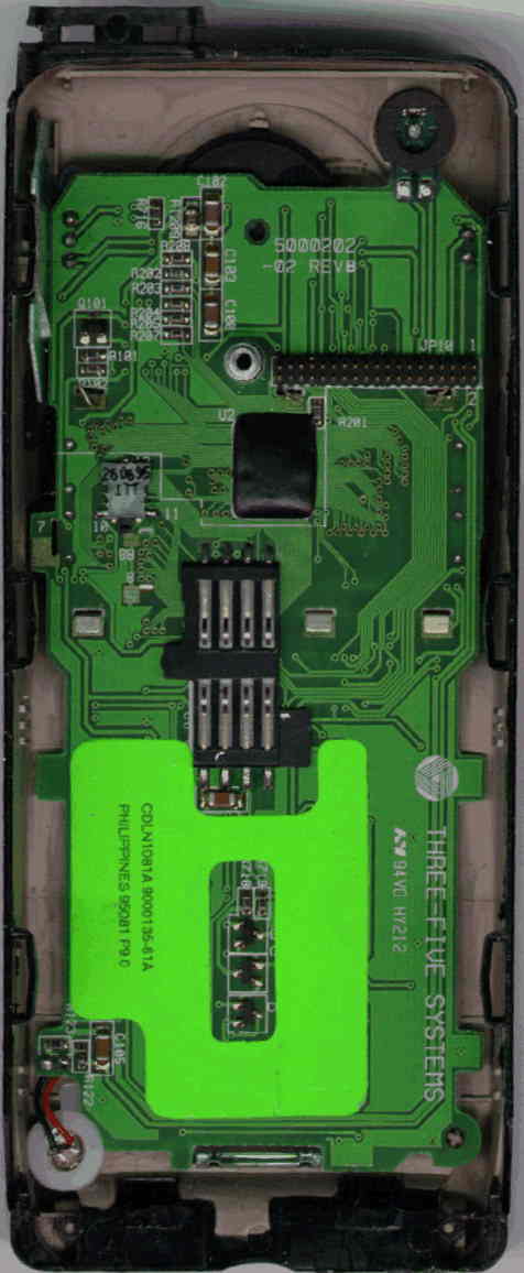
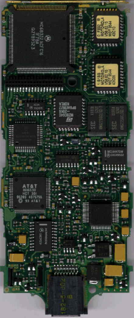
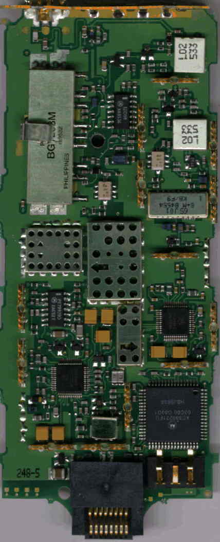
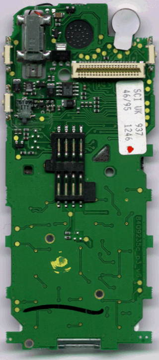
| Phone / Board | Keyb/Disp Front | Keyb/Disp Back | RF/Logic Front | RF/Logic Back |
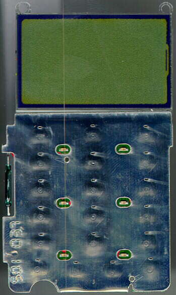
| 7500 (SUF1989F): | Picture | Legend | Picture | Legend | Picture | Legend | Picture | Legend |
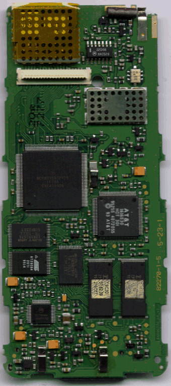
| 8200 (SUF1702B): | Picture | Legend | Picture | Legend | Picture | Legend | Picture | Legend |
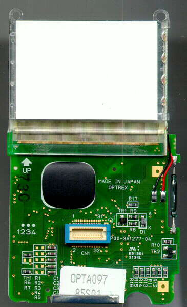
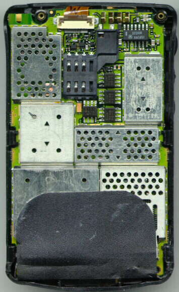
| d470 (SWF2248A): | Picture | Legend | Picture | Legend | ||
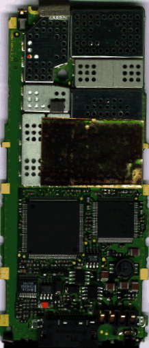
| Star (SUF?????): | Picture | Legend | Picture | Legend | Picture | Legend | Picture | Legend |
I have a 5200 that has the exact same hardware as the 7500's (Both HW 6.0) - the only difference is the software. It would be interesting to software upgrade the 5200 to a 7500 (But not legal because Motorola has the copyright on the software - so don't try that at home, kids !! ). It is amazing, that even though the 7500 hardware takes up much less space than the 5200, Motorola added a half centimeter of foam & plastic to make it just as bulky as the original 5200 !!!! A lot of the Motorola phones are IDENTICAL - the only difference is the EEPROM data, which can be transferred with a transfer card. The 8700/d460/d470 have the excact same RF/Logic board but a different housing and display board - however there is a 250 % price difference !! The 8400, 8200 and 6200's are also identical - same hardware (except the vibrator) and software (late 6200 and 8400 software is identical and the 6200 actually can be made to send SMS messages) but different eeprom flex or configuration data.
All the 5v Motorola phones I have seen use the Motorola 68332 32 bit microprocessor (16 MHz, but the clock runs at 13 MHz) - A member of the famous 68K family. Motorola use an AT&T (now Lucent) 1616 DSP - You can find the first 500 pages of documentation at Lucent. Motorola also has online datasheets on some of the chips. The 7500 and 8200 software is kept in two 29F040 4 Mbit FLASH EPROM. This totals 1 Mb which is mapped as 512k x 16 bits - In addition there is a 8K EEPROM, which keeps the IMEI, lock code, security code, user settings and phonebook - and the registers concerning SIM locking... If you have mapped some of these, I would like to know.
The later Mot phones : d460, d470, 8700, StarTAC &
Slimlite have a different design. They use a MC
68338 (that includes a RTC module) and 1616 but they
have a single 512k x 16 bits Flash RAM from AMD
(29LV800). There is a new IF chip, new power
transistior (Q904). Security against cloning has been beefed up
recently with the addition of a Dallas
DS2401 electronic silicon serial number. The serial
number in the dallas chip is incorporated in the checksum. The
DS2401 uses theibutton
standard for 1-wire communication with the MCU. DS2401 holds 8
bytes, adr 00 = 01 is family code (8 bit), adr 01-06 =
ACFA990XXXXX is serial number (64 bit) and adr 07 is CRC checksum
(8 bit) (Thanks Mee). The DS2401 application in the Motorola
phones have been sucessfully cloned using a PIC 12C509. This
allows good old EEPROM cloning on units with the DS2401 (Do not
ask me for the code, I do not have it!). The lastest versions of
the StarTAC 85 comes with a few suprises. The Lucent 1616 has
been replaced with the Lucent 1627. The speechcoder version us
now 12.xx instead of 11.xx. The old Motorola DSP's all had
version 5.xx. The IMEI also seems to be stored somewhere else,
since the addresses $52- are empty. Newer units (cd920/930) are
also storing the EEPROM configuration block checksum in another
location, since $0000 always is FFFF
The latest generation of motorola phones (d160, d520 and
cd920/930) have yet some new features. The d160 and d520 have the
same firmware. The d520 has a single PCB, a DS2401 mounted to the
left side of the keypad. It's in a DIL-6 package. The MC68338,
FLASH (INTEL 800B3) and RAM are all in nice little micro BGA
packages - very neat and cute and a bitch to replace ! The EEPROM
is however still in the TSOP package.
Besides the "off the shelf" chips mentioned above, motorola uses a number of application specific IC's (ASIC's). These are XC or SC circuits which are impossible to find any documention on.
I have a program written by Chefchen that will combine two 8 bit dumps to a 16 bit dump. This is very useful if you have dumped two ROM's (on the older phones) and want to have a look at the content (not all device programmers have that option). If you have swapped the bytes of each word, then Chefchens rotword is for you.
Here is a table of the RF intermediate frequencies (62,75,82,84) : (RX = VCO + IF 133MHz TX = VCO + IF 88MHz)
| VCO | TX | RX | |
| GSM Ch 001: | 802.2 MHz | 890.2 MHz | 935.2 MHz |
| GSM Ch 062: | 814.2 MHz | 902.4 MHz | 947.4 MHz |
| GSM Ch 124: | 826.8 MHz | 914.8 MHz | 959.8 MHz |
The IF 947.4Mhz is mixed with an 814.4Mhz signal, leaving a 133Mhz signal on which your modulated data is encoded. A local VCO also generates a 133Mhz signal and the two are mixed. The resultant being your modulated data (RXQ and RXI).On the 8700 Motorola changed all the Freq's so that the incomming RF signal is much higher (166Mhz) - this has eliminated some problems (due to bad design) with stray RF in the 110-144 MHz area (cancelling out the VCO so the RX path sees nothing). There is quite a history of design flaws. Here are some of the ones I have heard about: Battery charging circuitry fault which causes Li-Ion batteries to explode, Bad audio-loopback wich causes incomming speech to sound like a robot and problems with the Motorola DSP (Speech coder). Motorola lost their own internal contract to supply speech coders to their cellular division. There were some problems with overheating and the Cipher key being used.
The above information applies to the older phones, that used the MC68k processor family name. The new models like L, V and T series use the processor codenamed "WHITECAP". Whitecap is produced by TI and contains an ARM7 core. There are still several ASIC's, but they are becomming more and more integrated. For example the former BIC is now integrated into the Jekyll which soon will be yet again merged with the Hyde and then called CGAP2. An interesting thing here is that the DSC bus interface still is handled by hardware and not implemented in the firmware. The firmware now talks to the DSC bus over the SPI interface.
I would like to thank Carl for his great help with the hardware aspects !!!
EEPROM Information
I am trying to make a memory map of the 6200 EEPROM (should have a great similarity with other models) (obsolete).
TSOP-28 to DIL adaptors can be obtained from m2l electronics for just 60 USD - This is *very* cheap ! Have a look at www.m2l.com or contact mike@m2l.com
There are several checksums associated with the EEPROM:
The EEPROM contains a factory test flag. When this is set,
the phone will allow you to enter testmode without a SIM card
present. There has been an incident, where this flag was not
reset from the factory and a great deal of StarTAC's made it into
the shops. These units were able to enter testmode just by
holding down "#". I have compared the EEPROM dumps from
one of these phones with a normal one and successfully activated
the option on the "normal" phone. The Flag is present
at $003B, normally it is "03"(hex), but the
"instant testmode" phone has "13"(hex). This
byte is within the checksummed configuration block, so after the
nibble has been toggled, the phone will fail. This is easily
corrected with a clone card or by using the method described on
the testcard page.
On latest Mot phones (v and l series, for examples) the EEPROM is omitted and
"emulated" in the 2 mb FLASH program memory.
Mottool information
The Mottool is a utility that is written by Chefchen. If you
have dumped the EEPROM from a motorola phone, it will help you to
interpret the data contained in the EEPROM. You can view but
*not* change the IMEI, Lock code, Security code and several other
things. The latest addition to the program is the ability to view
the wake-up graphics of the 8700/StarTAC/Slimlite. To obtain
EEPROM dumps,you will need a device programmer with a TSOP-28
(most phones) or PLCC-32 (7500) adaptor and considerable
soldering skills... Download mottool
(16 kb).
SIM / SP - Lock Information
If you insert another SIM into a SIM locked phone it will first go "Enter PIN" and verify it. The parameter that is locked is the MCC & MNC which appear from the first 5 digits in the IMSI. A phone that is locked to a specific MCC/MNC will reject all other MCC/MNC pairs (with exception of 00101 that are reserved for testing). When rejecting a SIM, the phone will go "Enter Special Code Now" and let you enter 8 digits - Each number entered will appear as a "*" a wrong code will cause a "Wrong Code". It will however accept a test or clone card. A test card initialization (57#) will not remove the lock (that would be too easy, wouldn't it ?). After several attempts and the phone is restarted it will go "Please Wait to Enter Special Code" - It seems like overkill to put a time delay on top of an 8 digit code. If you punch 1 code a second it will take you in excess of 3 years to go through all the codes. When the unlocking attempt counter finally reaches zero, the phone will lock up and display "Phone Fail - Service!". There is AFAIK no way to calculate the Special code from the IMEI or MSN. It is stored "encrypted" (snicker snicker) in the EEPROM.
DSC bus and 3WIRE bus
Mot phones implement two different types of service bus: 3WIRE
bus (for analog AMPS or xTACS phones) and the DSC
bus (for digital GSM or PCN phones).
This page (and the butt plug pinout) used to mix up these two
buses, mainly because we (Stephan and Janus) were thinking that
Mot developed the same bus for all models.. but this was
wrong.
Analog phones implement the 3WIRE
bus, described in the famous patents that can be viewed
here. The bus connect to the two types of MCU which
latest analog phones are using (68HC11 as the main CPU, 68HC05 as
keyboard controller) and can be used to transfer personality,
MSN, NAM, and keyboard mapping. Please note that analog phones
are NOT software upgradable in the same manner of the digital
counterpart (they don't have any flash and there is no
"emmibox" for these phones, upgrading does require ROM
[de]soldering).
Digital phones implement the DSC
bus, that uses two data lines
(Uplink & Downlink) and one sense line
(DSC_Enable) used by the slave (ex. the phone) to trigger the ISR
(Interrupt Service Routine) of the master bus controller (ex.
emmibox, Cellect interface or hands free kit).
Uplink and downlink lines are self-clocking with a
Manchester-like encoding system and the IC that perform the
(en)coding, (de)interleaving is the famous BIC (Bus Interface
Controller, available in several revisions).
The BIC interfaces to the MCU with 8 data lines (D8-D15) and 4
address lines (A0-A4) on CPU32 based phones.
The DSC bus has a DHFA mode of operation. This is used with
Digital Hands Free Adaptors that have a CODEC and DSC bus driver
of their own and pass speech data to and from the phone via the
DSC bus (full duplex).
As already stated before, the former BIC functions are
implemented (software) in the TI MCU on latest phones (V series
& L series).
AN has provided the following information (Thanks!):
- The DSC bus level is about 400mV signal AC coupled on a DC
level
- It is a synchronous protocol with about 512 kbit/s
- It is some kind of biphase modulation, where clock and data are
multiplexed on one line. The stream is divided into bit cells,
where on every edge of a bit cell the level changes, if the bit
is a one the level changes a second time in the mid of the cell
too.
- There is a frame every 125 uS or 8 kHz. (everyone who knows PCM
telephony codecs will know this frequency. The start of every
frame is indicated by a 1.5 bit cells long cell. This violates
the usual clocking scheme and can easily be decoded. 8 bits * 8
channels * 8 kHz = 512 kHz. In fact it seems that Motorola built
a simple 8 channel PCM data bus on this interface. - Motorola
uses only the first channel for active data like handsfree
activation , radio mute status etc. Also it is possible to get
the digitized voice signals over this bus. Used i.e. on Startac
handsfree units.
I have also received a prototype construction of a DSC bus
driver / receiver.
If anyone would care to give it a try as well, you can find the diagram here. It
should be possible to make a DSP capable of this, so if you have
experience with these sort of things, please have a try.
If anyone can get me some
specifications / documentation on this, *please* contact me.
EMMIbox
EMMI means Electrical Man Machine Interface. EMMIboxes are not only made by Motorola. When phone manufacturers send a phone to ETSI for conformance testing, they must send a box along with a 25 pin Sub-D plug in one end that connects to the emmi interface on the ETSI computer that runs the test suite and the other end of the box goes into the phone. The box then must interface the phone to the EMMI interface. This can be very different. For some phones emmi commands can be sent directly to the phone (when a test card is inserted), so the emmi box is just a simple cable and on other phones (like motorola) it must have a bus driver and do a lot of command interpretation etc. etc. There are different "flavours" of motorola emmiboxes - some will allow you to service the phone (Firmware 30.xx), others allow IMEI and SP locking stuff (aka. restricted EEPROM elements)(Firmware 22.xx).
The EMMIbox is based on an 68332 MCU and a BIC 3.1 - just like the old GSM phones 6200 and 8200. While the phones do not need an external serial EEPROM (I2C) to store BIC configuration, the EMMIbox and HF kits does. This is to set the BIC up as DSC bus master. There is a DS2401 sicon serial number in there as well, but it seems not be used for anything in 30.xx and 22.xx firmware. This is the same situation with the 8K parallel EEPROM. It's noticable since it would be an interesting security feature to let the EMMI put it's serial number into the EEPROM of any phone it serviced in addition to keeping an internal log - well, it wouldn't be hard to bypass - but it would a cute way of keeping a check on what the box is being used for after hours.
SmartCELLECT cable
Here comes the smart part: you can't get an aftermarket/OEM cable (cd9x0 and earlier)! I got a report from Romaldo which disected his cable which turned out to contain a BIC and an ATMEL microcontroller. The cable includes a small multilayer PCB with SMD components soldered on both sides. On the upper side there is a 48 pins Motorola BIC (43E08, 13805). The RS 232 connector have 7 pins and use the following sigals: RI, CTS, GND, DTR, RTS, RXD and TXD. On the lower side of PCB there is a 44 pins ATMEL chip carrier labelled as follows: AT90S8515, 8AC - This is a 8-bit AVR microcontroller with 8K bytes In-System Programmable Flash. The new smartcellect cables for the V series are mere voltage level converters (BRAVO MOTOROLA). Hopefully we will soon see some cheaper alternatives.
Other useful info about Motorola GSM phones:
© 1998-2000 Janus Christian Krarup and Stephan Zegherd