How to enable the notorious 8700/8800/8900/6000e clock
The 2.7 volt Motorola GSM phones uses the MC 68338 as opposed to the MC 68332 that is used in the older 5 volt units. One of the diffrences between these two microcontrollers is the Real Time Clock Sub-Module (RTCSM). So the RTC module *is* present - before the clock can be enabled, some other things have to be in place: 1) An osciliator that provides the RTC module with a reference time-signal. 2) Software support to display and update the clock and 3) A Li battery together with a switching circuit that will make it supply the RTC module whenever the phone is powered down.
Here is a quote from the technical summary of the MC 68338 :
6.11 Real-Time Clock Submodule (RTCSM) with Low-Power Oscillator
The real time clock submodule provides a real-time clock independent of other CTM6 submodules. This time counter is driven by a dedicated low frequency oscillator (32.768 kHz) for low power consumption. The RTCSM contains a 15-bit prescaler and a 32-bit free-running counter, from which seconds, minutes, hours and days can be determined. The RTCSM can also generate interrupts at one second intervals. The low-power oscillator, prescaler, and counter portions of the RTCSM may be sustained by a separate power supply (VRTC ) for battery backup when VDD is off. The RTCSM and the low-power oscillator can be disabled for minimum power consumption on VRTC when VDD is powered off. This is useful for maximizing the shelf life of the standby battery.

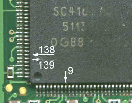
The manual describes how to solve the problem 1) of the missing time reference signal :The 32.768 kHz xtal is connected in serial with a 10 K Ohm resistor between the pins 139 (XRTC) & 138 (EXRTC) of the 68338. Both pins has a 1 pF capacitor between themselves and Gnd. It seems like the pin PF0/MODCLK (pin 67) has to be held HIGH at reset in order for the processor to use the external clock.
In practice, you can do by just connecting the XTAL
between pin 138 and 139 - it is difficult because of the hight
pitch of the pins, but the clock _has_ been enabled this way
(thanks Giuseppe). Remember to add the clock related menus with
MEDIT and activate the RTC with test mode command 8801#
A VERY FEW OF THE 8700's DOES HAVE THE
XTAL PER DEFAULT AND CAN BE ACTIVATED BY SOFTWARE ONLY
As for problem 3), the battery (+) should connect to VRTC (pin 9) It would seem nessecary to disconnect the battery (+) from VRTC whenever the radio is powered on, but it looks like the processor is able to do that by itself (another quote from the MC 68338 manual) :
6.14 RTCSM and RAMSM Standby Operation
The standby power switch in CTM6 monitors VDD and selects either VDD and VDDSYN or VRTC for the power source of the RTCSM and RAMSMs, depending on the level of VDD . When VDD is within the specified operating range, the RTCSM low-power oscillator is powered by VDDSYN and the RAMSMs are powered by VDD . VDD also provides power to the digital logic portion of the RTCSM, therefore both VDD and VDDSYN must be kept equal to each other for normal operation. When VDD and VDDSYN are powered down, the submodules are powered by VRTC and are in standby mode. In standby mode, the RTCSM continues to keep time if enabled. However, updates to the 15-bit prescaler and 32-bit free-running counter buffer registers are halted in order to conserve power. All RTCSM registers are write protected in standby mode to prevent loss of data in runaway situations. For the same reason, the RAMSMs are also write protected in standby mode. If the standby mode function is not required in a given application, VRTC should be powered from the VDD and VDDSYN supply. Unpredictable operation of the RAMSMs and RTCSM may result otherwise.

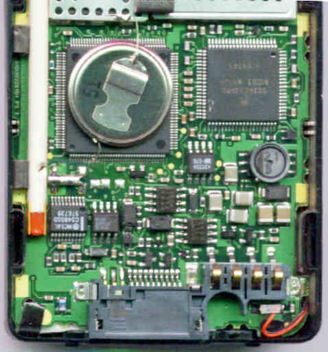
The best solution will probably be to just lift off the pin 9 and connect the battery so it's there all the time. If you do not lift the pin, the battery will drain fast and end up pulling the pin low and this can result in "phone fail see supplier" - as soon as the situation is corrected, the phone will work fine again. I would like to thank Ralph for proving the practical realization of all these "theoretical" ideas I have come up with here. Ralph has demonstrated his clever battery-adding procedure to me: Pin 9 is identified and heated with a clean soldering iron tip. The bit of solder that holds it to the pcb can be removed in this way and the pin can be lifted. Use a flat Li button cell (3v) - preferrable with soldering pins/legs on it. The small Li cell is filed or sandpapered a bit so the wires can be solder onto it. Be very careful since Li batteries hardly tolerate any heating at all before they will explode or leak ! The material of the battery body varies between the brands and can make soldering very hard. Varta batteries are in my experience hard to solder. Seizaiken cells are on the contrary easy to solder wires onto. The battery can be secured on top of the 68338 with a small blob of hot-glue. Take a look at the picture on the right for ideas (picture of my own 8900).
Here is another picture,
just to demonstrate, that where there is will, there is a way...
Actually, this is the first mod I have seen, where the caps have
been included - they will probably make the clock run at correct
speed. The clock tends to gain a little time when they are not
present (Sorry about the mocking Stephan, I just couldn't help
it.)
There are several different ways to add the crystal. I guess it depends on ones soldering skills and the type of crystal at hand. Personally, I used a crystal from at broken wristwatch. It was a lot smaller than anything I gould get at the electronics store - go ask at a clock repair shop - they will probably give you the guts from a broken watch for free. I placed the xtal directly on the two cpu pins, making the crystal body point outwards, away from the cpu. I scraped a bit of the PCB laquer away, to expose the copper layer. The crystal was then given a tiny blob of solder to secure it to the pcb. I had to cut a small hole in the antenna "straw" to make it able to go on top of the crystal.

On the 8900's the addition can be a real beauty (Picture at the right. The MCU is seen at the top, the red and grey tube is the straw that holds the antenna). Four pads below the MCU are meant to hold the crystal. The two on the left are ground pads that the crystal body can be secured to and the two pads on the right are for the xtal pins. It will also be easy to add capacitors, should one prefer so. The clock can run a bit too fast if the capacitors are left out, but in most cases it probably won't matter.
Siegbert reports: "I have soldered the xtal onto my 8900 and it worked fine. Placement of it was quite easy, you just wrap the whole thing into, for example heatshrink-tube and use two thin insulated wires, best from an old relay coil, to connect it to the ic. Length is absulotutely unimportant since the crystal is running at 32768Hz and wavelength is therefore beyond good and evil. The wires make the soldering job a lot easier and you can just put the crystal any place you want."
Madis reports: "Your page is very helpful for d160 as well. The RTC in my phone seems to be working fine."
Some d160/d170 (and probably others) firmware versions has a bug that interferes with the correct display of the clock. The RTC is read but somewhere alone the way, it is corrupted, resulting in erratic readouts. By applying a simple patch to the firmware (in this case 85.00.56) it can be corrected. Read Madis description here.
And another RTC patch for the d160/d170 by Clondike:
The "Show Time and Date" menu on d160/d170 is quite deep and it takes long time to reach this menu. I developed a patch for assigning the "Show Time and Date" menu to the shortcut menu. If you want to assign it to the shortcut [MENU] [1] [1], patch the word value $1183 (in Motorola endian, i.e. $11, $83) to the address $513B0. That's all. If you want to assign it to the shortcut [^]+[9], patch the four bytes $11 $83 $02 $6E to the address $47EA0. That's all. Of course, you have to need flash only a single memory block. (The firmware is the same as above: 85.00.56).
Visit this page for a description in Italian by JOSH. There is a picture with an alternative placement of the crystal.
© 1998 Janus Christian Krarup